Featured Posts

LightBlog

Saturday, October 5, 2019

Preventative Maintenance for Heating, Cooling and Refrigeration Systems(over)

4:24 AM 0
Preventative Maintenance for Heating, Cooling and Refrigeration Systems(over)

Preventative maintenance is a planned activity to clean, inspect, and test heating, cooling, and refrigeration equipment to ensure they run efficiently, reliably, and have a long service life. Most businesses practice reactive maintenance or “run it till it breaks” which has low upfront costs but will ultimately degrade equipment performance and reliability. Over 50% of business owners still operate with a philosophy of reactive maintenance.

The Basics:

  • Replace all filters quarterly
  • Inspect and clean evaporator and condenser coils quarterly
  • Inspect and lubricate fan motors quarterly
  • Replace all belts annually
  • 30 Point Maintenance Check (see below list)


Special Issues: 

Thermostat Settings :- Programmable thermostats can be confusing so if there are any questions these should be checked out. A lot of energy is wasted by not having the units “set back” when the building is unoccupied. Settings should be checked and adjusted to prevent excessive run time, maintain comfortable conditions during occupied hours, and achieve the maximum practical setback/setup during unoccupied hours. 
Economizer Damper Controls :-  These controls provide excellent energy savings. If operating properly they can save at least 10% of operating costs of the unit. However, if they are not inspected and tested at least twice a year there is a chance they might not be working properly. About half of all newly installed economizers don’t work properly. If they are not working properly they can waste more energy than they save.

30 Point Check List :-
  • Check system for proper refrigerant charge 
  • Check compressor amps 
  • Check condenser fan amps 
  • Check condenser coil 
  • Check contactor points 
  • Check capacitor
  • Check thermostat (level)
  • Check thermostat calibration 
  • Check temperature split at evaporator coil 
  • Check blower amps 
  • Check heat strip amps 
  • Check safety controls 
  • Check all electrical connections 
  • Check air circulation
  • Check for air leaks at plenum 
  • Check all visual leaks
  • Change filter if available 
  • Lubricate all moving parts where necessary 
  • Check and clean evaporator coil 
  • Flush or blowout condensate line 
  • Check for excessive vibration 
  • Level a/c condenser 
  • Check defrost control 
  • Clean, check & adjust condenser fan 
  • Check condensing temperature split at condensing coil 
  • Clean indoor blower 
  • Check the crankcase heater 
  • Check final performance


What does Pipeline Installation mean?

4:04 AM 0
What does Pipeline Installation mean?

Pipeline Installation refers to the laying of a pipeline to transport natural resources from the place of extraction to where they can be used or even within the place of their extraction. Laying pipeline on the seafloor can be challenging, especially when the water is deep. The most common methods of installing pipelines are S-lay, J-lay and Reel-lay. Other methods that are being used for installing pipelines are tow methods. The tow methods can be used to install pipelines from the shallow water depths to deep water depths.

The methods that are used to install pipelines are as follows:
  • S-lay: S-shaped curve is formed when the pipe curves downward while coming off the lay barge through the water until the pipe reaches the touchdown point. This method is different when compared to other methods because a stringer is used to support the pipe when it leaves the tensioner and the barge to avoid pipe buckling.
  • J-lay: This method is named due to its J-shaped curve formed after the pipe reaches the touchdown point. It is simpler and can be used easily in deepwater as compared to the S-lay method.
  • Reel-lay method: This method lowers the pipeline from the reel mounted on the vessel. It is able to install flexible pipes and smaller diameter pipes.
  • Tow methods are used to suspend pipes in water through buoyancy modules. One or two tug boats are used to drop the pipes into place. The tow methods consist of bottom tow, off-bottom tow, mid-depth tow and surface tow.

General installation requirements
Pipework must:
  • Comply with the durability requirements of Building Code clause B2 Durability
  • Be compatible with the support
  • Be installed to allow for thermal movement
  • Be protected from freezing by insulation, or being buried below the level of freezing
  • Be protected from damage
  • Be wrapped in flexible material or sleeved when penetrating masonry or concrete.

Thursday, October 3, 2019

How Expansion Valve's Works In Air conditioning? And Its Types....?

2:48 AM 0
What Is Expansion Valve ?


The expansion valve is situated in the liquid line between the condenser and the inlet of the evaporator.This is one of the basic components of the refrigeration system which are used to control refrigerant flow.It reduce the pressure & temperature of the refrigerant coming from the condenser as per the requirement of the system. And also helps to regulate the flow( Metering ) of refrigerant as per the load on the Evaporator.

Expansion valves do not directly control the ev​aporation temperature. Instead, they regulate the superheating by adjusting the mass flow of refrigerant into the evaporator, and maintain the pressure difference between the highpressure and low-pressure sides. The evaporation temperature depends on the capacity of the compressor and the characteristics and efficiency of the evaporator.
The term "low side" is used to indicate part of the system that acts under low pressure, in this case evaporator. high side is used to indicate part of the system that works under high pressure, in this case the condenser.


Basically Two types of expansion devices :-
1.Variable Restriction Type.
2. Constant Restriction Type.

1.Variable Restriction Type :-
In this, the extent of opening area of flow keeps on changing depending on the type of control. Three common types are :-
A. Automatic Expansion Valve (Pressure Control ).
B. Thermostatic Expansion Valve.
C. Float Valves.
i) High side Float valve In this it maintains the liquid at a constant level in the condenser.
ii) Low side Float valve In this maintains the liquid at constant level in the Evaporator.

2. Constant Restriction Type :-
Capillary Tube in which it is merely along tube with a narrow diameter bore.


AUTOMATIC EXPANSION VALVE :-

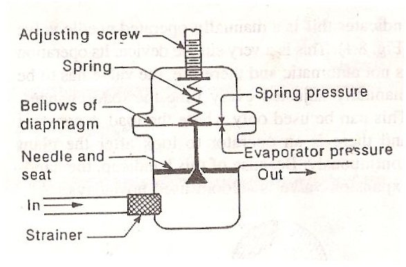
The Automatic Expansion valves works in response to the pressure changes in the evaporator due to increase in load( pressure increase) or due to decrease in load( pressure decreases).This valve maintains a constant pressure throughout the varying load on the evaporator controlling the quantity of refrigerant flowing into Evaporator.It consists of a needle valve, a seat, a diaphragm and a spring as shown in figure.
The opening of the valve in the seat is controlled by the two opposing forces.
A. the tension in the spring
B. The pressure in the evaporator acting on diaphragm.

Once the spring is adjusted for a desired evaporator pressure and given load, then the valve operates automatically with changing load conditions in the evaporator.

Assume the spring is adjusted initially to maintain a pressure of 1.5 bar in the evaporator at a given load. If the pressure falls below 1.5 bar due to decrease in load, the spring pressure will exceed the evaporator pressure and causes the valve to open more and increases the flow of refrigerant. If the pressure in the evaporator increases due to increase in load above 1.5 bar, the evaporator pressure will exceed the spring tension and valve move in closing direction. This reduces the quantity of refrigerant flow in the evaporator


THERMOSTATIC EXPANSION VALVE :-
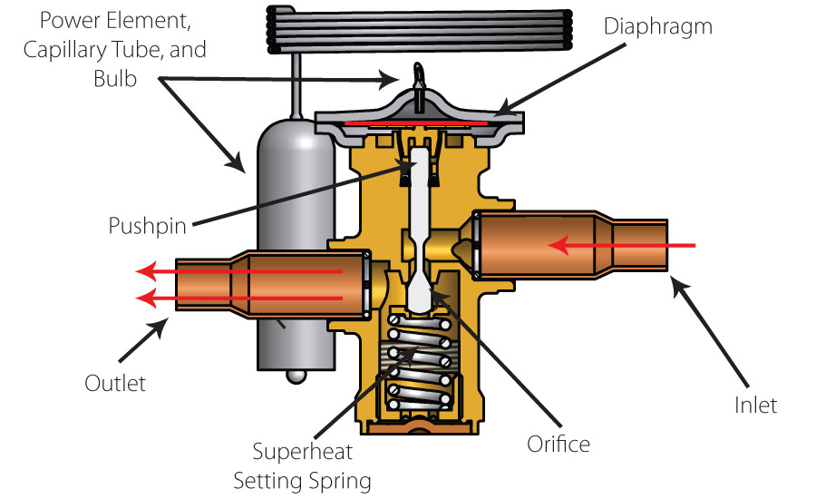
Thermostatic expansion valve uses the valve system to control the flow of liquid condensation in evaporative coils. The flow is controlled by pressure in the evaporator.

This type of metering device can work well when the load fluctuates and therefore is suitable for use in the air conditioning system. When the evaporator heats the valve, the high flow rate gives AMD when it cools down, it reduces the rate of flow.


It is also generally referred to as TXV, TEV or TX valve. There is a sensing bulb that detects the coil temperature and is usually located at high temperatures inside the evaporation.

To ensure proper sensing, the bulb must be clamped on the suction line. When the temperature of the evaporator increases due to the demand for cooling, the pressure in the bulb will also increase so that the spring is forced to open the valve.

when the temperature of the evaporation decreases due to lack of cooling demand, the bulb pressure will snap so that the spring causes the valve to close.

FLOAT VALVE :-
The float valve starts with the floating float in the liquid refrigerant. Low-side float and upper side-float are used to control flow of fluid refrigrants.


The lower side float helps to maintain continuous levels of liquid condensation in the evaporator. It opens when there is no fluid in externality. And when the vapor is liquid, it closes.The upper side is located next to the high pressure system of the float and keeps the condenser continuously in the refrigeration. When the compressor is operated, the condensed refrigeration flows into the float chamber and opens the valve.

This divides the refrigerant into evaporator where it is stored. As the liquid level comes in the float chamber, the valve will prevent the opening of the trail to turn the flow towards evaporation.


CAPILARY TUBES :-
Capillary tubes are the simplest of all refrigerant flow controls, and it is a is a fixed restriction type device with no moving parts. They normally consist only of a copper pipe, diameter 0.5 to 1.5 mm and length 1.5 to 6 m.It is along and narrow tube connecting the condenser directly to the evaporator.Its resistance to flow permits the capillary to be used as as pressure reducing device to meter the flow of refrigerant given to the Evaporator.


Capillary tubes can be found on small, high-volume commercial systems such as household refrigerators, but can also be used for larger systems if the operating conditions are relatively stable. The capillary tube is vulnerable to clogging, which is why a filter drier and filter are normally mounted before the inlet.

The low-pressure side of a refrigerant system with a capillary expansion device must be able to hold the whole refrigerant charge. When the compressor stops, the refrigerant will migrate to the cold, low-pressure side. Often, the low-pressure side is equipped with a liquid separator, which acts as a receiver, just before the compressor.

The refrigerant charge must also be carefully considered for capillary tube systems. An overcharged system will back up condensate into the condenser. This will eventually flood the condenser totally if the overcharge is sufficiently large or if there is a large change in operating conditions. Undercharge, on the other hand, will result in starvation of the evaporator, with hunting as a result.​


The advantage of a capillary tube are its simplicity , low cost and the absence of any moving parts. The disadvantages associated with this device is that the refrigerant must be free from moisture and dirt otherwise it will choke the tube and stop the flow of refrigerant. It cannot e used with high fluctuating load conditions.

Wednesday, October 2, 2019

Types of PIPING JOINTS

3:50 AM 0


PIPING JOINTS 


Joint design and selection can have a major impact on the initial installed cost, the long-range operating and maintenance cost, and the performance of the piping system. Factors that must be considered in the joint selection phase of the project design include material cost, installation labor cost, degree of leakage integrity required, periodic maintenance requirements, and specific performance requirements. In addition, since codes do impose some limitations on joint applications, joint selection must meet the applicable code requirements. In the paragraphs that follow, the above-mentioned considerations will be briefly discussed for a number of common pipe joint configurations.


Butt-welded Joints

Butt-welding is the most common method of joining piping used in large commercial, institutional, and industrial piping systems. Material costs are low, but labor costs are moderate to high due to the need for specialized welders and fitters. Long term leakage integrity is extremely good, as is structural and mechanical strength. The interior surface of a butt-welded piping system is smooth and continuous which results in low pressure drop. The system can be assembled with internal weld backing rings to reduce fit-up and welding costs, but backing rings create internal crevices, which can trap corrosion products. In the case of nuclear piping systems, these crevices can cause a concentration of radioactive solids at the joints, which can lead to operating and maintenance problems. Backing rings can also lead to stress concentration effects, which may promote fatigue cracks under vibratory or other cyclic loading conditions. Butt-welded joints made up without backing rings are more expensive to construct, but the absence of interior crevices will effectively minimize ‘‘crud’’ buildup and will also enhance the piping system’s resistance to fatigue failures. Most butt-welded piping installations are limited to NPS 21⁄₂ (DN 65) or larger. There is no practical upper size limit in butt-welded construction.


Butt-welding fittings and pipe system accessories are available down to NPS 1⁄₂ (DN 15). However, economic penalties associated with pipe end preparation and fit-up, and special weld procedure qualifications normally preclude the use of butt-welded construction in sizes NPS 2 (DN 50) and under, except for those special cases where interior surface smoothness and the elimination of internal crevices are of paramount importance. Smooth external surfaces give butt-welded construction high aesthetic appeal.


Socket-welded Joints

Socket-welded construction is a good choice wherever the benefits of high leakage integrity and great structural strength are important design considerations. Construction costs are somewhat lower than with butt-welded joints due to the lack of exacting fit-up requirements and elimination of special machining for butt weld end preparation. The internal crevices left in socket-welded systems make them less suitable for corrosive or radioactive applications where solids buildup at the joints may cause operating or maintenance problems. Fatigue resistance is lower than that in butt-welded construction due to the use of fillet welds and abrupt fitting geometry, but it is still better than that of most mechanical joining methods. Aesthetic appeal is good.


Brazed and Soldered Joints


Brazing and soldering are most often used to join copper and copper-alloy piping systems, although brazing of steel and aluminum pipe and tubing is possible. Brazing and soldering both involve the addition of molten filler metal to a close-fitting annular joint. The molten metal is drawn into the joint by capillary action and solidifies to fuse the parts together. The parent metal does not melt in brazed or soldered construction. The advantages of these joining methods are high leakage integrity and installation productivity. Brazed and soldered joints can be made up with a minimum of internal deposits. Pipe and tubing used for brazed and soldered construction can be purchased with the interior surfaces cleaned and the ends capped, making this joining method popular for medical gases and high-purity pneumatic control installations. Soldered joints are normally limited to near-ambient temperature systems and domestic water supply. Brazed joints can be used at moderately elevated temperatures. Most brazed and soldered installations are constructed using light-wall tubing; consequently the mechanical strength of these systems is low.


Threaded or Screwed Joints


Threaded or screwed piping is commonly used in low-cost, noncritical applications such as domestic water, fire protection, and industrial cooling water systems. Installation productivity is moderately high, and specialized installation skill requirements are not extensive. Leakage integrity is good for low-pressure, low-temperature installations where vibration is not encountered. Rapid temperature changes may lead to leaks due to differential thermal expansion between the pipe and fittings. Vibration can result in fatigue failures of screwed pipe joints due to the high stress intensification effects caused by the sharp notches at the base of the threads. Screwed fittings are normally made of cast gray or malleable iron, cast brass or bronze, or forged alloy and carbon steel. Screwed construction is commonly used with galvanized pipe and fittings for domestic water and drainage applications. While certain types of screwed fittings are available in up to NPS 12 (DN300), economic considerations normally limit industrial applications to NPS 3 (DN 80). Screwed piping systems are useful where disassembly and reassembly are necessary to accommodate maintenance needs or process changes. Threaded or screwed joints must be used within the limitations imposed by the rules and requirements of the applicable code.


Grooved Joints


The main advantages of the grooved joints are their ease of assembly, which results in low labor cost, and generally good leakage integrity. They allow a moderate amount of axial movement due to thermal expansion, and they can accommodate some axial misalignment. The grooved construction prevents the joint from separating under pressure. Among their disadvantages are the use of an elastomer seal, which limits their high-temperature service, and their lack of resistance to torsional loading. While typical applications involve machining the groove in standard wall pipe, light wall pipe with rolled-in grooves may also be used. Grooved joints are used extensively for fire protection, ambient temperature service water, and low pressure drainage applications such as floor and equipment drain systems and roof drainage conductors. They are a good choice where the piping system must be disassembled and reassembled frequently for maintenance or process changes.


Flanged Joints


Flanged connections are used extensively in modern piping systems due to their ease of assembly and disassembly; however, they are costly. Contributing to the high cost are the material costs of the flanges themselves and the labor costs for attaching the flanges to the pipe and then bolting the flanges to each other. Flanges are normally attached to the pipe by threading or welding, although in some special cases a flange-type joint known as a lap joint may be made by forging and machining the pipe end. Flanged joints are prone to leakage in services that experience rapid temperature fluctuations. These fluctuations cause high-temperature differentials between the flange body and bolting, which eventually causes the bolt stress to relax, allowing the joint to open up. Leakage is also a concern in high-temperature installations where bolt stress relaxation due to creep is experienced. Periodic retorquing of the bolted connections to reestablish the required seating pressure on the gasket face can minimize these problems. Creep-damaged bolts in high temperature installations must be periodically replaced to reestablish the required gasket seating pressure. Flanged joints are commonly used to join dissimilar materials, e.g., steel pipe to cast-iron valves and in systems that require frequent maintenance disassembly and reassembly. Flanged construction is also used extensively in lined piping systems.


Compression Joints


Compression sleeve-type joints are used to join plain end pipe without special end preparations. These joints require very little installation labor and as such result in an economical overall installation. Advantages include the ability to absorb a limited amount of thermal expansion and angular misalignment and the ability to join dissimilar piping materials, even if their outside diameters are slightly different.

Disadvantages include the use of rubber or other elastomer seals, which limits their high-temperature application, and the need for a separate external thrust-resisting system at all turns and dead ends to keep the line from separating under pressure. Compression joints are frequently used for temporary piping systems or systems that must be dismantled frequently for maintenance. When equipped with the proper gaskets and seals, they may be used for piping systems containing air, other gases, water, and oil; in both aboveground and underground service. Small-diameter compression fittings with all-metal sleeves may be used at elevated temperatures and pressures, when permitted by the rules and requirements of the applicable code. They are common in instrument and control tubing installations and other applications where high seal integrity and easy assembly and disassembly are desirable attributes.

Friday, September 27, 2019

Simple Calculation For Air Changes Per Hour

10:00 PM 0


An HVAC system is usually dimensioned based on the heat load of the space that requires cooling. But the required ventilation needs, depending on both application and occupation, are often overlooked. A simple air change calculation may assist in finding the right amount of fresh air ventilation.

Simple calculation :-

  • Use the table below to find the required amount of air changes per hour.
  • Calculate the volume of the space to be conditioned in either m³ (for SI units) or in ft³ (for I-P units). Calculate the required airflow: Airflow

Air changes table :-
The table below shows the required air change rate values based on data from The Engineering Toolbox [1], Nuaire [2] and Technisch Adviesbureau Betuwe [3].


Thursday, September 26, 2019

What is Humidity & Relative Humidity ? Effects of Relative Humidity ?

11:23 PM 0


If a closed container is partially filled with water, then some of the water molecules in the liquid will leave the surface of the water and become vapor. Once some water molecules are present as vapor they will also re-enter the liquid. After some time at constant temperature equilibrium will be reached where the same number of molecules are leaving and entering the liquid. At this equilibrium point the relative humidity of the water vapor is 100%.


What is Relative Humidity :-
Relative humidity (RH) is the percentage of water vapour present in the air relative to the amount that would be present in the equilibrium state.
The equilibrium point is temperature dependent. At higher temperatures the equilibrium occurs with more water vapor. If the container above was heated to 86ºF (30ºC) the water and water vapor would no longer be in equilibrium. The relative humidity of the vapor right after increasing the temperature would be 57%. This means that immediately after heating there are 57% as many water vapor molecules as would be present in the equilibrium state.

It is the above process that causes dry air in buildings. As cold incoming air is heated, its relative humidity value drops. Therefore moisture must be added to attain an acceptable level of humidity within the building.

The equilibrium point is temperature dependent. At higher temperatures the equilibrium occurs with more water vapor. If the container above was heated to 86ºF (30ºC) the water and water vapor would no longer be in equilibrium. The relative humidity of the vapor right after increasing the temperature would be 57%. This means that immediately after heating there are 57% as many water vapor molecules as would be present in the equilibrium state. Figure 2: Relative Humidity after Heating It is the above process that causes dry air in buildings. As cold incoming air is heated, its relative humidity value drops. Therefore moisture must be added to attain an acceptable level of humidity within the building.


Effects of Relative Humidity :-
The reasons for humidifying dry air vary from one building to another and from one geographic area to another, however there are three fundamental reasons. 
These are: 
  • Static Electricity 
  • Poor Moisture Stability 
  • Health and Comfort Static 
1.Static Electricity :-
Electricity Static electricity is a condition caused by stationary charges of electricity and is a major problem in most unhumidified areas. Since static electricity is caused by friction, particularly when the elements in friction are dry, the problem increases proportionately with the speed of production machinery. Without sufficient humidification, high-speed machinery might well defeat its own purpose. Reduced efficiency is frequently the result of static electricity. 
  • In the Printing industry presses must self-feed paper evenly, one sheet at a time at very high speeds. When the static electricity causes sheets of paper to stick together, the paper bunches, the feeding becomes uneven, and eventually the paper jams the presses. 
  • In the Textile industry static electricity causes the yarns to adhere to each other, the shuttles miss threads and improper weaving patterns result. 
  • In offices, static electricity can disrupt operations and increase operating costs. In many photocopiers, sheets of paper stick together and jam the machine, wasting time and paper. Severely jammed equipment may even require service calls. 
  • In Computer rooms and data processing areas, the lack of humidity results in static electricity that causes problems such as circuit board failure, dust buildup on heads, and storage tape breakage. 
  • Static electricity can also be dangerous. Sparks caused by static are extremely hazardous in locations such as hospital operating rooms where flammable gases are present. Many flash fires – even explosions - are caused by static electricity.
  • Controlling Static Electricity - Maintaining relative humidity above 35% is one important measure that can be taken to reduce static electricity. 


Controling Static Electricty :- 
One of the easiest and most common methods of minimizing static electricity is to increase the relative humidity level. Electrostatic charges do not dissipate through moist air, but through a moisture film that is absorbed on the charged surfaces. This moisture film decreases the surface resistance and causes static charges to be drained. This effect is most pronounced at RH above 30-35% and it also corresponds with a decrease in ozone production (a by-product of electrostatic discharge). Static electricity is a problem that should be of primary concern to any manufacturing plant interested in running efficiently and accurately.


2.Moisture Stability :- 
When air is heated the relative humidity will decrease. When this occurs the rate at which water molecules leave objects containing water or the rate at which water evaporates is increased. All hygroscopic or fibrous materials either lose of gain moisture in direct relation to the relative humidity of the surrounding air. 
Moisture stability is the ability of a material to maintain a level of moisture content despite fluctuations in the humidity of the environment. Many materials give off, or take on moisture rapidly which can result in serious damage to the material or the process in which it may be involved. The drying out of a material can result in product deterioration, while conversely, a dry material can also suffer damaging side effects of moisture regain. In many cases, product deterioration is directly related to the lack of moisture stability 
Below Table  gives the hygroscopic regain of some common hygroscopic materials. Hygroscopic regain is defined as the amount of water a completely dry material will absorb from the air. It is expressed as a percent of the dry weight. (For example the weight of completely dry timber will increase by 9.3% if it is stored at an RH of 50%) 


  • Products such as vegetable, cut flowers, fruit and many grocery items cannot be brought back to original quality once they have lost their moisture. By installing an efficient humidification system this costly loss of products can be avoided. Many food processors humidify their plant and storage areas and are able to store fruits and vegetables for months without any loss of product quality or weigh. 
  • For any product that requires a certain percentage of moisture to maintain its quality, loss of that moisture reduces its valve. Some products can be brought back to their original condition by returning the moisture to them. However, among those that cannot reabsorb moisture to regain their lost quality are fruit and vegetable products, paintings and art objects. 
  • Deterioration caused by loss of moisture is also a problem for treasures such as antiques, rare books, and works of art, all of which are susceptible to damage caused by moisture loss. It causes antiques, paintings, paper and book bindings to crack, warp and deteriorate. Fortunately, most libraries and museums are well aware of the need for controlled humidity to protect their collections. They know that proper humidity control is a very inexpensive preventive measure that will avoid costly and often impossible restorations. 
  • A specific moisture content in materials is essential to the quality of products produced by a wide range of manufacturers of hygroscopic or fibrous materials. Wood, paper and textiles are examples of materials particularly affected by changes in content. If these materials have a correct moisture content when they arrive at a plant, and if they are used immediately, they will respond properly to the manufacturing process. But problems can be anticipated if the materials are stored in a dry atmosphere. 
  • Paper provides a good example of the effects of dry air and the lack of moisture stability. When it is stored under dry atmospheric conditions, moisture from the outer layers and edges of the stacks escapes into the air. The moisture loss is much more rapid from the outer edges than from the center of the stacks. The result is not only curled stock, but also uneven moisture content, which creates printing and processing problems. 
  • If moisture stability in the surrounding atmosphere is the answer to a manufacturing operation, then complete humidification of the plant and storage areas is an absolute necessity. Humidification is the best and least expensive way of maintaining moisture stability. If the air surrounding the material is maintained at a proper and constant relative humidity level, so that no moisture is emitted or absorbed by the materials, then the products will remain stable in both moisture content and dimension. 
  • Ideally, humidification equipment should be installed in raw material storage areas, manufacturing facilities, and finished goods’ storage rooms, for full control of the product moisture content.


3.Health and Comfort :-
During the heating season, inside air dries to the point where the humidity is substantially lower or comparable to that of the Sahara Desert. The effect on people is to dry out nasal and throat membranes. For employees this means more susceptibility to colds and virus infections. The subsequent increased absenteeism proves costly for any employers. Another aspect of comfort is the fact that humidity in the air makes a room feel warmer, so there will be fewer requests to have the thermostat turned up. 
Most employers provide air conditioning for employee comfort and productivity during the hot days of summer. Adding humidification for full winter comfort and productivity is just as important as air conditioning in the summer months. In fact, it is one of the most important functions of the complete air conditioning or “total comfort” system.

  • The advantage of conditioning the interior space of a building to increase productivity and reduce the downtime of machinery has been documented many times. Unfortunately it is usually equipment, such as computers and communications systems, that is placed in separate climate controlled rooms, while the majority of employees have temperature control only. 
  • Temperature control must be combined with humidity control to maintain proper comfort parameters in an office environment. More than 75% of all I.A.Q. problems start with a comfort complaint. If this is not rectified, the employees will continue to complain and become less productive. 
  • Temperature control alone does not take into account the physiological aspects of the employees. As demonstrated in Figure 3, indoor RH variations above and below the 40-60% range have a dramatic effect on the comfort and well being of employees. Humidity conditions above this range are usually controlled easily by the normal dehumidification process of the air conditioning system. However, as the cold, dry weather of winter approaches or in arid climates, the indoor RH can easily drop well below the recommended 40% parameter. It is not uncommon to find relative humidities in the 10-15% range in most offices during this period. This low RH creates comfort, productivity, and absenteeism problems costing immeasurable dollars to employers worldwide. Studies conducted by Dr. George Green of the University of Saskatchewan indicates that increasing the indoor RH from 20 to 30% will reduce absenteeism by 15%. This, along with the productivity increase that can be gained from additional comfort result in a real economic benefit from general office humidification.

What is PDMS(Plant Design Management System) & Advantages of PDMS ?

12:05 AM 0

Its a product by AVEVA is known as a multi-defined, user-defined, and multi-user software that is used in designing and engineering along with the construction projects. It is a 3D design software that helps the designers to work in a team or alone into their own 3D environment. They can also able to view the designs of others as well.
  • It is a customizable, multi-user and multi-discipline, engineer controlled design software package for engineering.
  • Multiple users or designers can work at the same time.
  • 3D Design Software for plant design from Aveva Plant
  • Fully interactive, color-shaded design setting
  • Positioning & selection of parametric components from a wide-ranging catalogue
  • Status Management function for visual highlighting
  • Configure integrity checking & Clash checking
  • Offers automatic, configurable generation of wide-ranging reports & drawings
  • .NET API & PML for system customization
  • Integrate with other AVEVA Plant interface products & applications.
Advantages of PDMS :-
  • To see the actual model of the plant in the software with exact dimensions.
  • To reduce the material from 10% to 30% from the manual calculations of the material of the project.
  • We can save time while designing the project in pdms. Designing project in 2d like AutoCAD taking much more time as compared to pdms.
  • In pdms we check the piping clashes of the piping, equipment and other inter disciplines.
  • Designing is of piping is more accurate. Because we can see all space around the plant.
  • Very less chance of rework, if the designing is done on the pdms. This helps us to save fabrication time on the yard.
  • he accuracy is more in pdms as compared to other 2D software.
  • PDMS can generate the material take off report of each every component in the pdms, which is not possible in 2d software. From the material takeoff report we can get exact quantities of material which are going to use in the plant for fabrication purpose. We can order that material as the material take off reports.
  • From pdms we can run isometric drawing of the piping for fabrication purpose automatically. In AutoCAD isometric drawings are taking too much time.
  • Modification of any pipe, equipment or structure can be done easy as compared to other software.
  • PDMS is user friendly with other software like Caesar II for stress calculations and With AutoCAD to import the data from pdms to these seawares.
  • We can be design supports for piping in the hanger and supports module. Pdms is commands based software. While operating the software we required some command to use the software.

Wednesday, September 25, 2019

What is Piping Engineering and Its Scope in Mechanical Industries ?

11:58 PM 0

Before we Learn about What is Piping Engineering and scope of Piping Engineering In Mechanical Based Industries . First lets Know about What is Pipe and Piping Process ?

When a fluid is required to be transferred from one location to other, pipe is required. A pipe is considered as a pressure tight cylinder which is used to convey fluids under pressure through materials of commercially available designation.


What is a Pipe ?
A pipe is a tubular section or hollow cylinder, usually but not necessarily of circular cross-section, used mainly to convey substances which can flow — liquids and gases (fluids), slurries, powders, masses of small solids. It can also be used for structural applications; hollow pipe is far stronger per unit weight than solid members.
Piping systems act like a nervous system for the flow of fluid in the huge network of any industry around the globe.


What is Piping ?
Piping is an assembly of pipe, pipe fittings, valves, instruments and specialty components.
Piping is divided into three major categories:
  • Large bore pipe generally includes piping which is greater than two inches in diameter.
  • Small bore pipe generally includes piping which is two inches and smaller in diameter.
  • Tubing is supplied in sizes up to four inches in diameter but has a wall thickness less than that of either large bore or small bore piping and is typically joined by compression fittings.

What is Piping Engineering ?
The most interesting branch of science in Mechanical Engineering is Piping .Piping Engineering has great scope all over the World. Piping is more often referred as ‘HALF SCIENCE & HALF ART’. 

Piping Engineering is a specialized engineering discipline that deals with the planning and layout of a robust piping system with an aim to effectively transport fluids, such as liquids and gases, from one point to the other within a process plant or a commercial building.

Owing to the fact that pipes are quite elementary to our day-to-day needs and to industries such as Oil & Gas, Energy, Construction, Manufacturing, Chemical etc., there is always a need for trained and skilled Piping Engineers who can support the design, implementation and maintenance of complex and large-scale piping systems for these industries.Piping engineering is all about designing, fabricating and constructing lines for conveying fluids.
Importance of Piping Engineering:

  • To maintain pressure difference (Δp)
  • To maintain temperature difference (Δt)
  • To maintain flow rate (Δq)
Piping Engineering includes production of various drawings and documents. It is very important for any industrial plant. Some of the activities for Piping Design and Detailed Engineering :- 3D modeling, plot plan, stress anaysis, support engineering, piping modeling, support modeling and many more.

The Best software used for Piping Engineering by us:-

  • SP3D(Civil engineering/Electrical Engineering/Mechanical Engineering)
  • PDMS
  • PDS
  • CAESAR-2
Moreover, with increasing modernisation and industrial growth, the Piping Industry is also poised for greater heights which will result in more employment opportunities for Mechanical Engineers who are trained in this high potential domain.

Scope of Work & Responsibilities of Piping Engineer :-

  • The piping department of an engineering and construction company generally begins with the piping and instrumentation diagram (P&ID).
  • Process department prepares process flow sheet, which begins with the chemical reaction and after carrying out material and energy balance and equipment selection, which is further utilized to prepare a first version of P&ID.
  • This means that one can now begin actual plant design. Going through steps of plot plan and equipment layout, the next step is to start designing piping system for material transport.
  • In our course, we will be adopting a building block concept, where we will begin with pipes selected by line sizing and hydraulics of pumps and compressors used to transport material. These pipes are “connected” using pumps and compressors, add to it the valves, safety devices, measuring instruments and control components and first rough sketch of piping structure would be over.
  • However a scientific and systematic approach is developed over the years and design codes and practices evolved are used to go through a step-by-step procedure to come up with a piping system structure.
  • Learning this systematic science is the aim of this course. No such structure will be approved by engineers unless its stress analysis is done including stress at the connecting components such as nozzles, flanges, pipe supports and so on.
  • We will be using pipe stress software to find if designed structure can sustain static, dynamic and combined stresses
  • General flowcharts for piping design procedures in parts at least are provided during the actual exercises.
  • Thus, process and piping are becoming a major force in engineering, procurement and construction (epc) companies as part of Engineering IT culture being developed and justify a growing need for qualified engineers to take up this profession.

Standard & Codes that need to be followed while Designing or Manufacturing any Piping System

11:54 PM 0


There are certain standard codes that need to be followed while designing or manufacturing any piping system. Organizations that promulgate piping standards include:

  • ASME - The American Society of Mechanical Engineers - B31 series
  • ASME B31.1 Power piping (steam piping etc.)
  • ASME B31.3 Process piping
  • ASME B31.4 Pipeline Transportation Systems for Liquid Hydrocarbons and Other Liquids and oil and gas
  • ASME B31.5 Refrigeration piping and heat transfer components
  • ASME B31.8 Gas transmission and distribution piping systems
  • ASME B31.9 Building services piping
  • ASME B31.11 Slurry Transportation Piping Systems (Withdrawn, Superseded by B31.4)
  • ASME B31.12 Hydrogen Piping and Pipelines
  • ASTM - American Society for Testing and Materials
  • ASTM A252 Standard Specification for Welded and Seamless Steel Pipe Piles.
  • API - American Petroleum Institute
  • API 5L Petroleum and natural gas industries—Steel pipe for pipeline transportation systems.
  • CWB - Canadian Welding Bureau
  • EN 13480 - European metallic industrial piping code
  • EN 13480-1 Metallic industrial piping - Part 1: General
  • EN 13480-2 Metallic industrial piping - Part 2: Materials
  • EN 13480-3 Metallic industrial piping - Part 3: Design and calculation
  • EN 13480-4 Metallic industrial piping - Part 4: Fabrication and installation
  • EN 13480-5 Metallic industrial piping - Part 5: Inspection and testing
  • EN 13480-6 Metallic industrial piping - Part 6: Additional requirements for buried piping
  • PD TR 13480-7 Metallic industrial piping - Part 7: Guidance on the use of conformity assessment procedures
  • EN 13480-8 Metallic industrial piping - Part 8: Additional requirements for aluminium and aluminium alloy piping.
  • GOST, RD, SNiP, SP - Russian piping codes
  • RD 10-249 Power Piping
  • GOST 32388 Process Piping, HDPE Piping
  • SNiP 2.05.06-85 & SP 36.13330.2012 Gas and Oil transmission piping systems
  • EN 1993-4-3 Eurocode 3 — Design of steel structures - Part 4-3: Pipelines
  • AWS - American Welding Society
  • AWWA - American Water Works Association
  • MSS – Manufacturers' Standardization Society
  • ANSI - American National Standards Institute
  • NFPA - National Fire Protection Association
  • EJMA - Expansion Joint Manufacturers Association

CODES AND STANDARDS USED IN PIPING ENGINEERING

11:40 PM 0


WHY IT IS REQUIRED ?
  • Selection of proper material and detail out the material specification.
  • Standardization can and does reduce cost, inconvenience and confusion that result from unnecessary and undesirable difference in systems.
  • One of main objective of each code is to ensure public and industrial safety.

DEFINITIONS:-
Industry standard are published by professional societies, committees and trade organizations. It can be broadly classified into the following categories......
  • CODE
  • STANDARDS
  • RECOMMENDED PRACTICES

CODE :-
A group of general rules r systematic procedures for design, fabrication, installation and inspection prepared in such a manner that it can be adopted by legal jurisdiction and made into law.

STANDARDS :-
Documents prepared by a professional group or committee which are believed to be good and proper engineering practices and which contain mandatory requirements.

RECOMMENDED PRACTICES:-
Documents prepared by a professional group or committee indicating good engineering practices but which are optional.

STANDARDS FOR PIPING DESIGN:-
  • ASMEB31.1: Powerpiping
  • ASME B31.2: Fuel Gas piping.
  • ASME B31.3: Process piping.
  • ASME B31.4: Pipeline Transportation system for liquid Hydrocarbon and other liquids
  • ASMEB31.5: Refrigeration piping.
  • ASME B31.8: Gas Transmission and Distribution piping.
STANDARDS FOR PIPING COMPONENTS:-

PIPES:
  • B36.10M: Welded and Seamless Wrought Steel Pipes
  • B36.19M: Stainless Steel Pipes
Flanges:-
  • B16.5: Steel Pipe flanges and flanged fittings
  • B16.47: Large diameter steel flanges
  • B16.48: Steel Line Blanks
  • API 5L: Line Pipe.
FITTINGS:-
  • B 16.9: Factory Made Wrought Steel Butt- Welding Fitting
  • B 16.11: Forged Steel Fittings, Socket-Welding & Threaded

VALVES:-
  • API 594: Wafer And Wafer Lug And Double Flanged Check Valve
  • API 599: Metal Plug Valves-Tanged & Welding Ends
  • API 600: Steel Gate Valves - Flanged and Butt Welding Ends, Bolted and Pressure Seal Bonnet
  • API 6D: Pipe line valves, End closures,Counselors end swivels
  • API 593:Ductile Iron Plug Valves- Flanged ends.
  • API 600: Steel gate valves.
  • BS 1414: Steel Wedge Gate Valves flanged Cud Butt Welding Ends)
  • BS 1868: Steel Check Valves) flanged & Butt Welding Ends)
  • BS 1873: Steel Globe, Globe stop cud Check Valves )Flanged & butt welding ends.
  • BS 5351: Steel Ball Valves
  • BS/EN 593: Specification for Butterfly valves
  • BS 5352:Steel Wedge Gate, Globe and Check Valves 50mm and Smaller
  • BS 5353:Steel Plug Valves
  • Bd 6364:Valves For Cryogenic Services.
GASKETS:-
  • B 16.53:Metallic Gaskets for Steel pipe flanges, ring joint, Spirel-Wound, and gasketed.